 |
|
|
 |
|
|
|
Improving the CG-5 Equatorial Mount
Declination Axis, Part 3
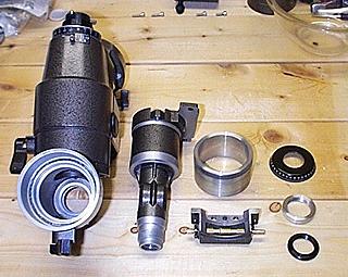
Cleaning
Dip each plastic washer into the solvent and carefully wipe it clean using a cotton cloth. Do the same with the ring nut and retaining ring. The idea is to remove as much of the old grease as possible, along with dirt and metal shavings left over from the manufacturing process.
Deburring and Polishing
There are numerous metal-to-metal and metal-to-washer bearing surfaces inside the Dec assembly. Run your finger across all of these surfaces, feeling for rough spots. To make the mount operate smoothly, you'll want to smooth out any rough spots you find.
It's sometimes difficult to determine whether or not a particular surface actually comes in contact with another surface. If in doubt, put a small dab of grease on a surface, slip the component into place, and rotate it. Then remove the component and see if the grease has been distributed across the surface. If it has, you can be fairly certain that the surface should be smoothed and polished. You don't want to waste time and effort on surfaces that don't make contact with anything.
Inside my CG-5, there were some very rough, almost jagged burrs. I used a sharpening stone to file them as smooth as possible.
Next, I used the Crocus cloth to polish all of the bearing surfaces. I spent a lot of time at this, perhaps more than necessary. I used small pieces of Crocus cloth so that I could reach into various nooks and crannies.
In my mount, some of the plastic washers had been roughened by contact with jagged metal. I used a hobby knife to gently scrap and shave off all rough spots I found on the washers. I was able to get them quite smooth. If you do this, use care not to cause further damage.
When everything is smoothed and polished to your satisfaction, clean the parts with your solvent and a clean cotton cloth.
Applying Grease
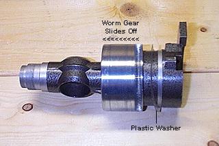
Apply grease to both sides of the two large washers that go on opposite ends of the worm gear. Put a few evenly-spaced dabs of grease on both sides of each washer. Grease the portions of the Dec shaft that bear on the inside of the worm gear. Slide the first large washer, then the gear into place on the Dec shaft. Place the second large washer into its location in the Dec housing.
Next, grease the bearing surfaces on the bottom end of the Dec shaft. Grease the entire outside of the worm gear (or the entire inside of the Dec housing). Make certain the gear teeth of the worm gear are completely greased. Put the Dec lock button into place, then slide the Dec shaft into the housing until the parts are fully seated.
To check whether the internal surfaces are sufficiently smooth, assemble the components, rotate the Dec shaft a few times, them pull the shaft from the housing. Examine the bearing surfaces and washers to see if the grease is evenly distributed, with no gaps. Pay special attention to the large washers on the worm gear. If the dabs of grease have been spread around the whole washer after a few turns of the Dec shaft, the bearing surfaces are probably smooth enough.
Adjustments
When adjusting the ring nut, bear in mind that the assembly will loosen up a bit after a period of use. If it is too loose now, it will only become looser later. There is a very fine line between too loose and too tight. You will find yourself making very small changes in the tightness of the ring nut to achieve the best compromise.
Worm Shaft End Play
On both of my CG-5s, there were several very small, very thin plastic washers in the worm assemblies. These washers are nearly invisible when buried in the thick factory grease, so it's easy to miss them. Look carefully!
Another description of this adjustment comes from fellow CG-5 owner Jim McKay. Note that the worm assemblies on Jim's CG-5 contained no plastic washers! This is indicative of the variation you can expect between different examples of the CG-5.
Worm Gear Mesh
The small set screw between the two larger silver hex head screws on the worm assembly controls how deeply the worm meshes with the teeth of the worm gear inside the mount. If the gears mesh too tightly, the worm shaft will be stiff and difficult to turn. If the two gears do not mesh enough, the axis will have backlash and "slop."
Turning the set screw clockwise pushes the worm farther from the worm gear, loosening the axis. Turning the set screw counter-clockwise lets the gears mesh more deeply, tightening the axis and reducing backlash. Proper adjustment consists of making small changes in the depth of the set screw until you achieve a good compromise between ease of motion and lack of backlash. Note that this sounds counter-intuitive (turning the screw clockwise to loosen up the axis), but it is correct.
Start by applying some grease to the worm and re-attach the worm assembly to the housing. Replace and tighten the four silver hex head screws, starting with the two on either side of the set screw. Try to tighten these two screws equally. Then tighten the other two hex head screws holding the worm assembly. Now grasp the upper end of the housing and turn the shaft.
If it is too tight and does not move freely, loosen the four silver hex head screws and turn the set screw a fraction of a turn clockwise to loosen up the axis. Re-tighten the four hex head screws and check the axis again.
If it is too loose and wobbly, loosen the four silver hex head screws and turn the set screw a fraction of a turn counter-clockwise to tighten up the axis. Re-tighten the four hex head screws and check the axis again.
As little as a tenth of a turn of the set screw can make a noticeable difference in the tightness of the gears. In addition, tightening the four hex head screws deforms the castings slightly, pressing the gears together and causing them to mesh a little tighter. The soft metal used for the castings is easily deformed by tightening the screws.
So you must use some trial and error to get it right. You want the worm tight enough against the worm gear so that the axis doesn't wobble, yet not so tight that the worm shaft is hard to turn.
Fellow CG-5 owner Bob Supler suggests lubricating some of the screws in the worm assembly:
I didn't do this, but based on discussions with Bob, it seems like a good idea. When I need to adjust the worms again, I'll follow Bob's advice.
Between adjusting the tightness of the ring nut and adjusting the worm assembly, it's easy to spend an hour or more on each axis. That's what it takes to find the best compromise between stability and ease of motion. Don't skimp on this part of the project. Failing to properly adjust the mount can negate all the hard work you've done to clean, smooth and re-grease it. It's well worth your time.
Re-Assembly
You've completed work on the declination axis. Congratulations!
| ||||||||||||||||||||||||||||||||||||||||||||||||||||||||||||||||||||||||||||||||||||||||||||||||||||||||||||||||||||||||||||||||||||||||||||||||||||||||||||||||||||||||||||||||||||||||||||||||||||||||||||||||||||||||||||||||||||||||||||||||||||||