 |
|
|
 |
|
|
|
Build a Barn Door Tracker
Drive Electronics
How was the 100 Hz drive frequency determined?
First of all, I carefully selected the dimensions of the mount and the pitch of the drive screw such that the screw must turn exactly once per minute (1 rpm) to track at the sidereal rate.
We also know the characteristics of our motor and gearbox:
motor step angle = 1.8°
This gives us the information we need to calculate the required drive frequency:
desired drive rate = 1 rpm = 360°/min.
To "rewind" the mount to its starting point, I used a drive frequency of 800 Hz. Why 800 Hz? The 800 Hz "rewind" frequency was selected because it was conveniently available from the same circuit used to generate the 100 Hz drive frequency.
When you construct your own drive circuit, it must be customized for your motor's step angle and the amount of gear reduction you employ. Both the frequency of the quartz crystal and the ratios of the divider chain must be selected to produce the required frequency. My recommendation is to use Grover's circuit and, if necessary, change the crystal and divider chain to produce the frequency required for your mount and motor.
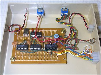
I built the driver circuit on a Radio Shack general-purpose PC board and housed it in a plastic 5¼" floppy diskette case. The three connectors are for the 12-volt DC power source, the motor, and the limit switch (to shut off the drive before the drive board runs into the base board). The two switches are for power on/off and reverse/rewind. A small LED indicates power on.
Here's a close-up of the circuit board.
When considering the electronics circuit, it's useful to think of it as three blocks.
Although Grover's (and my) circuit uses a crystal oscillator in the first block, you can use something as simple as a 555 timer chip (in its astable configuration) and still achieve excellent results. In fact, for a long time I used a 555-based oscillator circuit to drive the stepper controller chip of my equatorial mount with very good results.
A 555 circuit may not be as accurate as a crystal-controlled circuit and may be affected by temperature changes. But the 555 circuit is inexpensive, simple to build, and adjustable over a wide range of frequencies, making it easy to set up for ANY motor and gearbox combination. Here is a nice tutorial with 555 astable information.
Regardless of what type of circuit you choose for the oscillator block, the switching and driver blocks remain the same. If you wish, you can even build the oscillator and driver portions on separate circuit boards. I found this useful while testing my circuit.
| ||||||||||||||||||||||||||||||||||||||||||||||||||||||||||||||||||||||||||||||||||||||||||||||||||||||||||||||||||||||||||||||||||||||||||||||||||||||||||||||||||||||||||||||||||||||||||||||||||||||||||||||||||||||||||||||||||